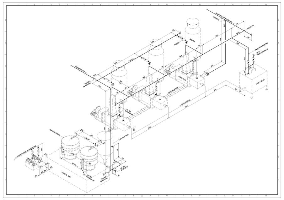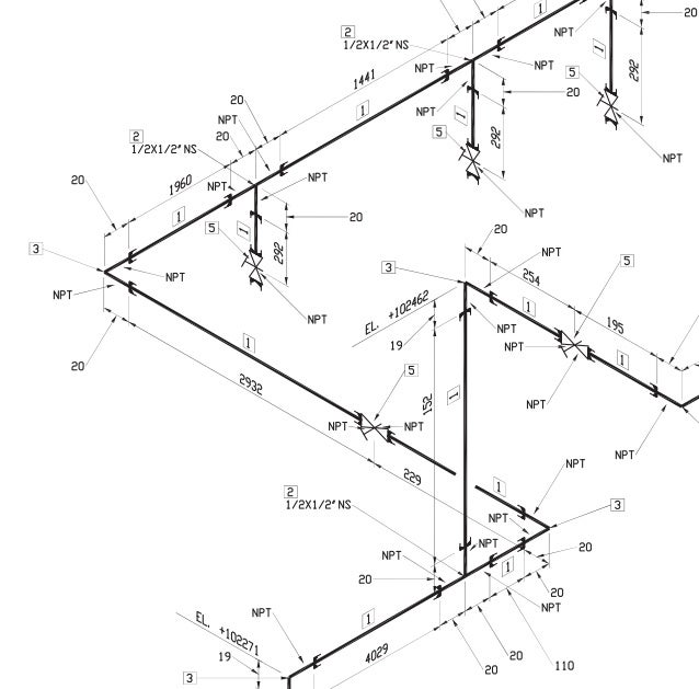
The image below show the presentation used in drafting. Isometric, Plan and Elevation Presentations of a Piping System I've never tried, but I think for orthographic views maybe 50 drawings are needed to show the same as the Iso's. for a complex pipeline system, 15 isometrics must be drawn. In a orthographic view it is not a problem if the pipe runs in one plane, but when a pipe in two or three planes to be drawn, a orthographic view can be unclear.Īnother reason why isos are preferred, is the number of drawings that for orthographic views should be made.įor example. The simplicity with which a pipe isometric can be drawn is one reason to made iso's.Ī second reason to made isometrics if a pipe should be drawn in several planes (north to south, then down and then to the west, etc.), orthographic views really not an option. The red lines show the pipe, the black dots are the butt welds and A, B and C are the dimensions of front to center line and center line to center line. The isometric view shows the same pipe as in the orthographic view.Īs you can see, this drawing is very simple and quick to implement. Isometrics are the most important drawings for installation contractors during the field portion of the project. Piping isometrics are often used by designers prior to a stress analysis and are also used by draftsmen to produce shop fabrication spool drawings. In very complex or large piping systems, piping isometrics are essential to the design and manufacturing phases of a project. Piping isometrics are generally produced from orthographic drawings and are important pieces of information to engineers.

Vertical lengths of pipe are calculated using elevations, while horizontal lengths are caculated using north-south and east-west coordinates. Pipe lengths are determined through calculations using coordinates and elevations.


Because iso's are not drawn to scale, dimensions are required to specify exact lengths of piping runs. The Iso, as isometric are commonly referred, is oriented on the grid relative to the north arrow found on plan drawings. Usually, piping isometrics are drawn on preprinted paper, with lines of equilateral triangles form of 60°. The symbols that represent fittings, Valves and flanges are modified to adapt to the isometric grid. Isometrics are usually drawn from information found on a plan and elevation views.

Unlike orthographics, piping isometrics allow the pipe to be drawn in a manner by which the length, width and depth are shown in a single view.


 0 kommentar(er)
